8. Ventilators
- Classification
- Ventilator modes and settings
- Modes for spontaneous ventilation
- What is protective ventilation?
- Typical ventilator alarms
- New features
- Turbine ventilators
- Piston ventilators
- Flexibility (New modes)
- Accuracy at lower tidal volumes
- Compliance and leak testing
- Fresh gas decoupling versus compensation
- Suitability for low flows
- Current models
- Dräger Apollo, Perseus, Fabius GS
- GE Aisys, Avance, Aespire, Aestiva
- Other; Paragon, Anestar
- Older or obsolete ventilators
Classification
-
Power source (either compressed gas or electricity) is the force that drives gas into the patient's lungs.
- o Bellows & Servo ventilators use compressed gas from pipeline.
- Dräger uses electricity to drive a piston or turbine.
- All use electricity for electronic sensors and computer control mechanisms.
-
Drive mechanism - generates inspiratory flow

|
Bellows ventilator. Click on the link to see the larger version.
Bellows vents (e.g. Aisys) classified as double-circuit, pneumatically driven. Double-circuit means that a pneumatic force (driving gas) compresses a bellows, which empties its contents (patient gas from flowmeters and vaporizer) into the patient. "Bag in bottle." Driving gas is oxygen or air.
|

|
Piston ventilator. Click on the link to see the larger version.
Piston ventilators (Apollo, Fabius GS) do not require driving gas. An electric motor moves a piston containing patient gas, compressing the gas and driving it into the patient's lungs. Thus, piston (or turbine) ventilators are economical of wall oxygen (only using it for metabolic needs, and not to compress a bellows).
|
|
Turbine ventilator. Click on the link to see the larger version.
Turbine ventilators (Dräger Perseus)- electric motor used to drive a high speed turbine (blower) which creates inspiratory pressure and flow. (Imagine a super-powerful hair dryer.) This technology has been used in ICU ventilators for some time, and is just currently its way into anesthesia equipment. It is an efficient means of generating inspiratory flow.
[1],
[2]
|

|
Servo ventilator on Flow-i. Click on the link to see the larger version.
Servo-type ventilators (e.g. Maquet Flow-I, Flow-e & Mindray A9) use compressed gas to create the force driving inspiration. Pipeline gas (marked "Reflector O
2" in the image) creates the force of inspiration, pushing gas from the volume reflector through the absorber & into the lungs.
|
-
Cycling mechanism - ventilators are time cycled in control mode. Newer ventilators add modes that support weaning during emergence (SIMV, pressure support, CPAP, etc.).
- Modern ventilators use solid state electronics for timing.
- In volume control mode (
How much?), flow is constant, and inspiration ceases when the set tidal volume is delivered to the breathing circuit (not necessarily the patient- the two quantities may differ due to compliance losses or leaks!). Inspiration may also stop when a maximum pressure is reached. Peak inspiratory pressure varies with changes in compliance, and must be watched.
- In pressure control mode (
How hard?), flow is generated to establish and maintain the target pressure for a certain time, then exhalation begins. Delivered tidal volume varies with changes in compliance, and must be watched.
-
Triggering is either by time (breaths/min setting), or by the patient's spontaneous efforts.
Bellows classification
|
|
Standing (ascending) bellows. Click on the link to see the larger version.
To remember the classification: "ascend" and "descend" have "e" in them - so look at them during
expiration. Ascending bellows ("standing") ascend during expiration (modern type - preferred) and descending bellows ("hanging") descend during expiration.
Ventilator relief valve gives 2 - 3 cm water PEEP (true for all mechanical ventilators with standing bellows). The ventilator relief valve (spill valve) allows scavenging ONLY during the expiratory phase.
|
|
"Hanging" bellows on the Anestar. Click on the link to see the larger version.
The hanging design is chosen by a (very) few manufacturers. Newer hanging bellows housings, unlike older designs, lack an internal weight, and sense when the bellows do not return to the full "down" position. These factors, plus integration of disconnect alarms based on chemical (capnograph), and mechanical (pressure, volume, and flow sensors) apnea detection, make hanging bellows designs safe. However, placement of the hanging bellows below the writing surface can make visual detection of disconnects difficult. Also it is less easy to determine if the patient is breathing spontaneously in addition to the rate set on the mechanical ventilator. The user must rely more on the pressure and capnography waveforms as opposed to the bellows. Water may gather in the descending bellows (lessening tidal volume and creating an infection risk) but this tendency may be counteracted by heating the absorber head.
|
Ventilator modes and settings
The biggest improvement in current ventilators is their flexibility in modes of ventilation, including modes which support assisted and spontaneous ventilation. Various types of pressure controlled ventilation (PCV) allow more efficient and safe ventilation of many patients.
The improvement in ventilator sensors and electronic controls means that switching of circuits (for example, to a non-rebreather for small children) is not as necessary. This is safer because potential misconnections are avoided, and quicker besides. The latest direction the manufacturers have taken is offering modes (such as pressure support) that will support or assist spontaneous ventilation, seen in anesthesia with much greater frequency due to the advent of the laryngeal mask airway and more brief ambulatory procedures. Although ventilators provide more accurate V
T in VCV (due to compliance and leak compensation- see below on this page), this mode is currently used much less frequently than when VCV was the only mode available.
Terminology for modes and controls is not standardized, and can be confusing. The table below gives Dräger and GE terminology for ventilator mode classification.
Ventilation Modes
;
Click on the small image to see a larger image of the pressure & flow waves.
Control
Label
Drager (GE)
|
Pressure, Flow waves |
Definition |
Volume Mode
VC-CMV (VCV)
|
|
Volume control- Continuous mandatory ventilation: A set number of breaths/minute (f or RR) which are time cycled and machine triggered. Tidal volume (V
T) is controlled, and independent of changes in lung mechanics. Inspiratory flow is constant. Peak inspiratory pressure varies and should be kept as low as possible, certainly < 35 cm water.
PEEP may be added to most modes.
|
Volume Mode
VC-SIMV (SIMV-PSV)
|
|
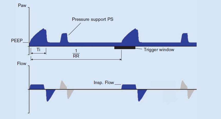
Volume control- Synchronized intermittent mandatory ventilation: The mandatory breaths are synchronized with the patient‘s own breathing attempts, if these generate enough negative pressure within a trigger window. If no breathing attempt is detected during the trigger window, the machine-triggered mandatory breath is applied. Thus the minute volume (MV or V
E) remains constant over time. The patient can breathe spontaneously at PEEP level during the expiratory phase, and these breaths can be pressure-supported using PSV.
|
Volume Mode
VC-CMV-AF or Autoflow (PC-VG)
|
|
Autoflow applies the set V
T with the minimum pressure required. If Resistance (R) or Compliance (C) changes, the pressure adapts gradually, by automatic adjustment of inspiratory pressure and flow. AF may be applied in any volume controlled mode; it is very similar to
pressure control with volume guarantee (PC-VG) which is used in the Aisys and Avance.
|
Pressure Mode
PC-CMV (PCV)
|
|
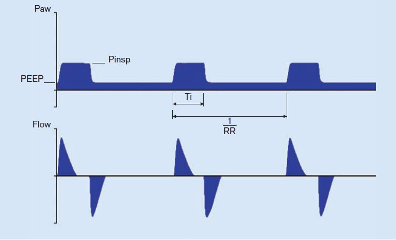
Pressure control- Continuous mandatory ventilation: controls inspiratory pressure (Pinsp), PEEP, and f (breaths/min). The pressures are maintained which may compensate for leaks. Tidal volume (and V
E) vary with changes in patient effort, compliance and airway resistance. The flow generated varies. Flow is high at first to produce the set Pinsp early, and it is less later in inspiration to maintain the set pressure through the inspiratory time (Ti). PEEP, Volume guarantee, SIMV, and PSV may be added to pressure control ventilation.
|
Pressure Mode
PC-SIMV (SIMV-PC)
|
|
Pressure control- Synchronized intermittent mandatory ventilation: PC-CMV, with the mandatory breaths delivered in synch with patient efforts.
|
Pressure Mode
PC-CMV-VG (PC-VG + SIMV)
|
|
Pressure control with volume guarantee: Volume guarantee may be used with pressure-controlled modes such as PC-SIMV, and PC-CMV. Volume guarantee ensures that for all mandatory breaths the set V
T is applied with the minimum pressure necessary. If the Resistance (R) or Compliance (C) changes, the pressure adapts gradually over a few breaths to restore the set V
T.
|
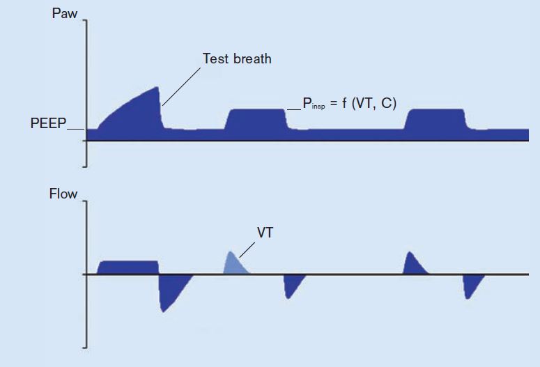
Pressure Mode
PC-PSV (PSVPro; CPAP/PSV)
|
|
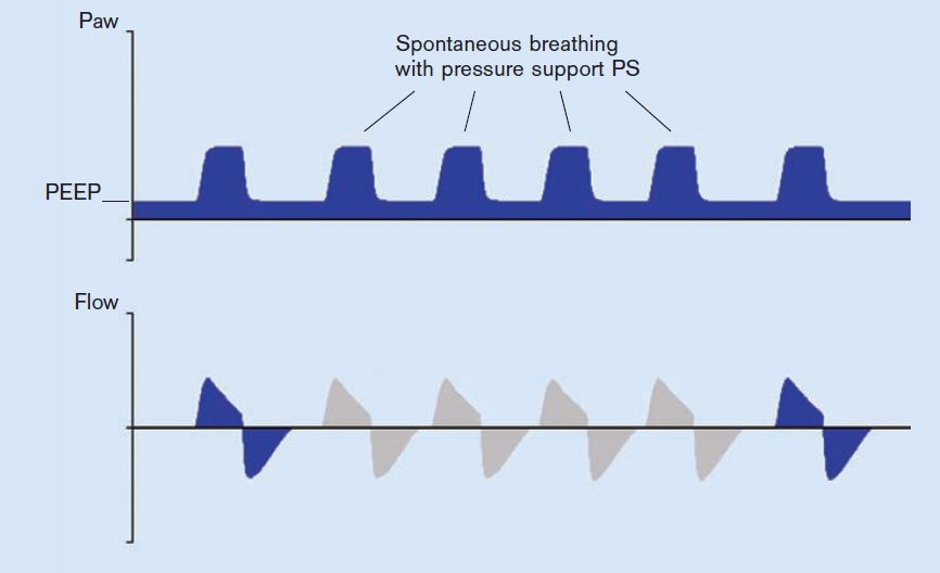
Pressure support ventilation: The patient can breathe spontaneously at PEEP level. Every detected inspiratory effort is supported. The absolute level of pressure support is defined by Psupp. The duration of inspiration is flow-cycled and thus depends on the lung mechanics of the patient. The patient determines the number, timing and duration of the pressure-supported breaths. If the breathing frequency of the patient is lower than the set backup frequency (RR) or there is no spontaneous breathing, machine-triggered flow-cycled mandatory breaths with the set pressure Pinsp (PCV) are applied. The backup settings (Pinsp, RR) are controlled by the operator. V
T results from the pressure difference between PEEP and Psupp, the lung mechanics and the breathing effort of the patient. If the Resistance (R) increases, or Compliance (C) of the lung decreases, V
T and V
E will decrease.
|
Pressure Mode
PC-BIPAP (None)
|
|
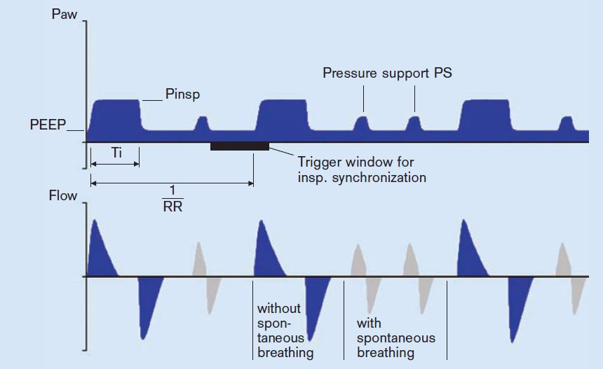
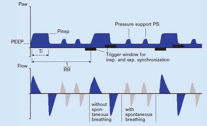
Biphasic positive airway pressure: the patient can breathe spontaneously at any time, but the number of mandatory breaths is specified. Mandatory breaths are synchronized with any breathing attempts of the patient. If no spontaneous breathing attempt is detected during the inspiratory trigger window, the machine-triggered mandatory breath is applied. The V
T results from the pressure difference between PEEP and Pinsp, the lung mechanics and the breathing effort of the patient. If the Resistance (R) or Compliance (C) of the lung changes, V
T and V
E also vary. During spontaneous breathing at PEEP level, the patient can be supported using PS.
|
Pressure Mode
PC-APRV (None)
|
|
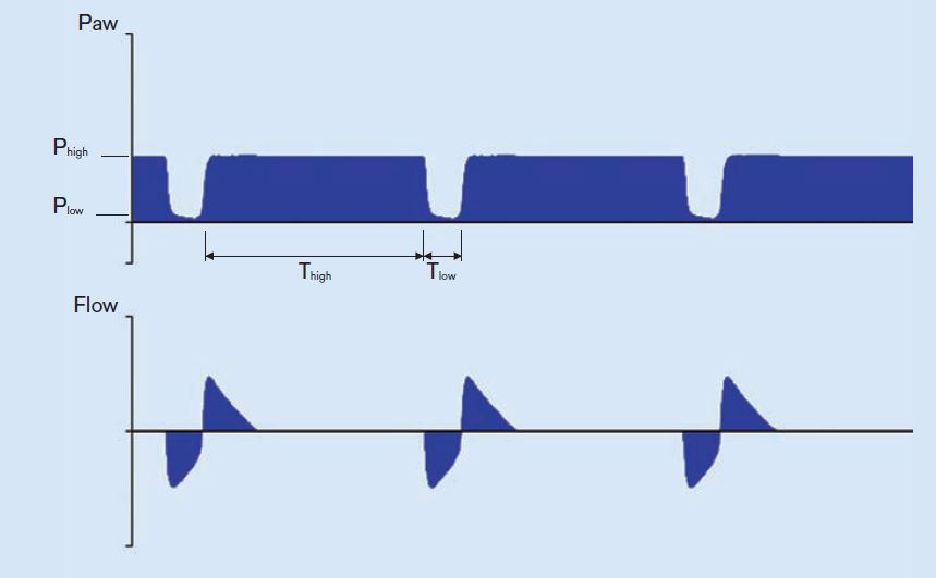
Airway Pressure Release Ventilation: the patient’s spontaneous breathing takes place at the upper pressure level "P
high". P
high is maintained for the duration of T
high (time at high pressure). To execute an active expiration and support CO
2 elimination, the pressure is reduced (to P
low) for a brief period (T
low). The alternation between the two pressure levels is machine-triggered and time cycled. V
T expired during the relief times (at P
low), results from the pressure difference between P
low and P
high and the lung mechanics. If the Resistance or Compliance of the lung changes, the V
T and thus the V
E also vary.
|
Spontaneous mode
SPN-CPAP (CPAP or PSV)
|
|
Spontaneous- Continuous positive airway pressure: In SPN-CPAP, the patient breathes at the PEEP level. Compared to the atmospheric pressure, the airway pressure is increased during the complete breathing cycle.
|
Sources
[3]
| Manufacturer |
Model |
Ventilator type |
Modes |
| Dräger Medical |
Perseus A500 |
Turbine |
Manual/spontaneous, PC-CMV, PC-BIPAP, VC-CMV, VC-CMV/AF, VC-SIMV/AF (Autoflow), Auxiliary common gas outlet, SPN-CPAP/PSV, PC-BIPAP/PSV, VC-SIMV/AF/PSV, PC-APRV. |
| Dräger Medical |
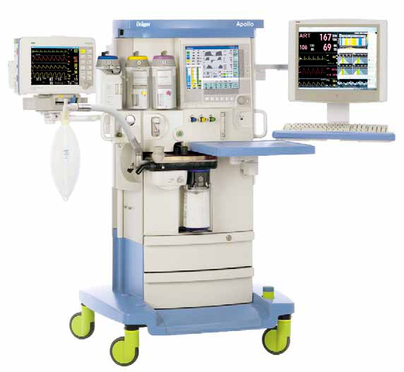
Apollo |
Piston |
Manual/spontaneous, VC-CMV, PC-CMV, PSV, VC-CMV/AF (Autoflow). |
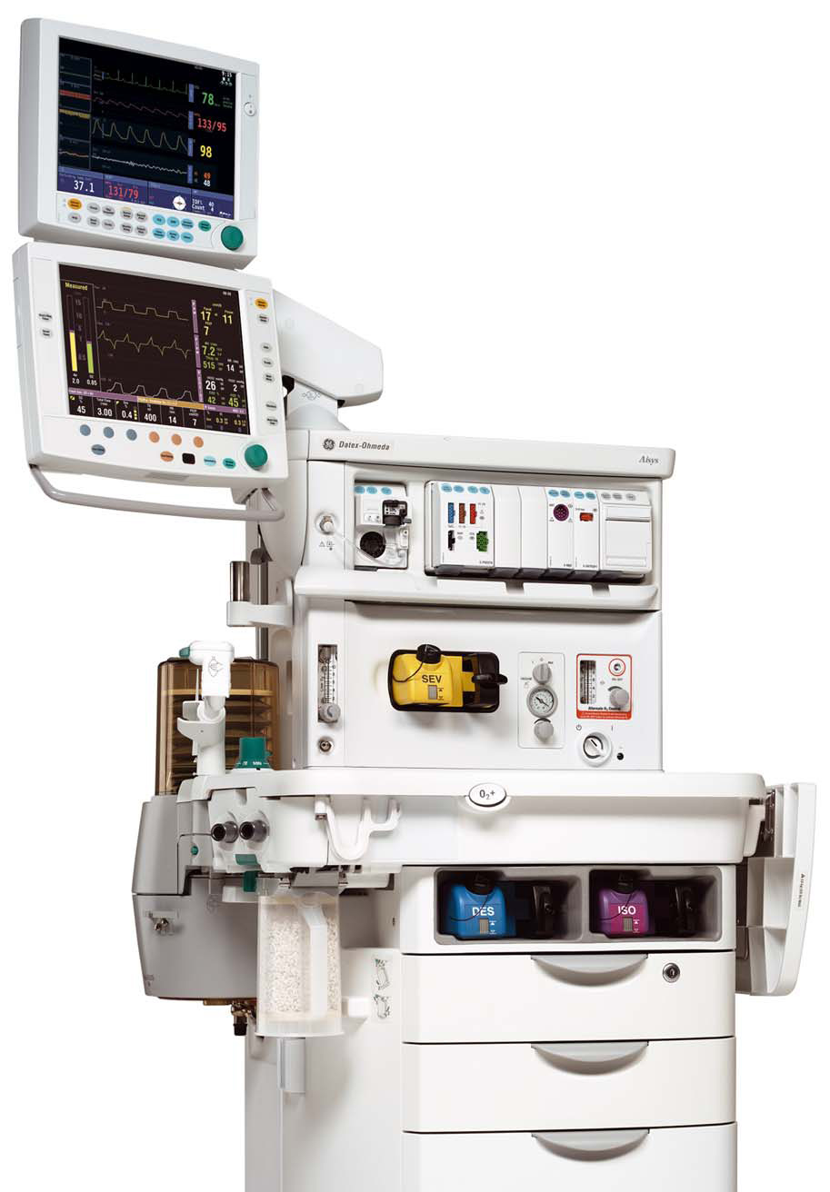
| GE Healthcare |
Aisys-CS
2
|
Bellows |
Manual/spontaneous, VC-CMV, PC-CMV, PCV-VG, SIMV (with VC-CMV, PC-CMV, or PC-VG), SPN-CPAP/PSV, Auxiliary common gas outlet. |
| Maquet (Getinge) |
Flow-i |
Servo (gas-driven with volume reflector) |
Manual/spontaneous, VCV, PCV, PSV, PRVC (pressure-regulated volume control), SIMV, Auxiliary common gas outlet. |
| Mindray |
A9 |
Servo (gas-driven with volume reflector) |
Manual/spontaneous, VCV, PCV, SIMV, PCV-VG, CPAP/PSV, APRV, Lung recruitment tool, High Flow Nasal Cannula, Auxiliary common gas outlet. |
Sources
[4]
Modes
not
currently implemented in anesthesia ventilators
- Assist-control (VC-AC or PC-AC): A volume-control mode in which the patient can trigger breaths, each of which is delivered at the full set V
T. Or a pressure control mode in which the patient can trigger breaths, each of which is delivered at the full Pinsp. Patient triggered breaths will add to the V
E, sometimes remarkably so.
- Mandatory minute volume (VC-MMV) guarantees that the patient always receives at least the set minute volume. Time-cycled, machine-triggered mandatory breaths are synchronized with the breathing effort of the patient. If the spontaneous breathing is insufficient to achieve the set V
E, machine-triggered time cycled mandatory breaths are applied. As the patient breathes more, the ventilator gives less breaths. During spontaneous breathing at PEEP level, the patient can be pressure-supported using PSV.
- Volume support-In SPN-CPAP/VS, the patient breathes at the PEEP level. Airway pressure is above atmospheric during the complete breathing cycle. If the patient is too weak to manage the complete breathing effort independently, a volume support can be added. Here a target V
T is set and the necessary pressure for it applied. Every detected inspiration attempt at PEEP level triggers a pressure-supported, flow-cycled breath. If the lung mechanics change, the applied pressure varies to keep the set V
T constant.
- High frequency settings are not yet supported on anesthesia delivery systems.
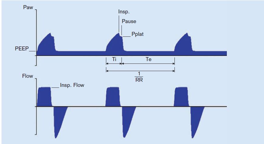
Volume Controlled -Continuous Mandatory Ventilation (VC-CMV)
|
|
Waves- VC-CMV. Click on the link to see the larger version.
All ventilators offer volume controlled ventilation (VCV is the GE terminology). In this mode, the set volume is delivered at a constant flow. The peak inspiratory pressure is allowed to vary, and it does, according to the patient's compliance and airway resistance. Volume is adjusted to avoid atelectasis, and rate is adjusted for reasonable end-tidal carbon dioxide while monitoring the peak inspiratory pressure.
|
The values controlled and kept at the set target value are the V
T and respiratory rate (RR, breaths/min, f). This results in the minute volume (V
E = f x V
T). The duration of the inspiratory phase is defined by the inspiration time (Ti). If the inspiratory flow is so high that the set breathing volume is reached before the set inspiratory time (Ti) has passed, there will be a pause in inspiration.
VC-CMV, once universal, is now used much less frequently, in view of better alternatives such as pressure conytrol modes.
Settings for VCV in an adult
- V
T 5-7 mL/kg
ideal body weight or
predicted body weight
- Ideal body weight kg = 25 x Height (meters
2)
- Predicted body weight kg (also known as Devine or simple formula)
- (male) = 50 + (0.91*(Ht cm -152.4))
- (female) = 45.5 + (0.91*(Ht cm -152.4))
- RR 6-12 (or more) breaths per minute (bpm), titrate to end tidal CO
2
- PEEP 5 cm H
2O to start (add if trouble oxygenating, obese, adverse position (Trendelenburg), or especially at the lower end of the tidal volume range above)
- Autoflow, SIMV, PEEP, or PSV may be added to VC-CMV.
Volume control- Synchronized intermittent mandatory ventilation (VC-SIMV)
|
|
Waves- VC-SIMV. Click on the link to see the larger version.
VC-SIMV detects spontaneous breaths (if any) and delivers volume-controlled breaths in synch with the patient's inspiratory efforts. This helps maintain minute ventilation, while avoiding breath-stacking or bucking. If too many (or too few) synchronized breaths are delivered, adjust trigger window and sensitivity.
- Trigger window- what percentage of the expiratory pause the vent monitors for patient effort
- Sensitivity- How much negative inspiratory force the patient must generate to trigger a breath from the ventilator
|
Patients may breathe at will between ventilator breaths. The AIsys/Avance ventilators in VCV mode support any "in-between" spontaneous breaths with pressure support ventilation (PSV), resulting in a mode GE calls SIMV-PS.
Pressure Control -Continuous Mandatory Ventilation (PC-CMV)
|
|
Waves- PC-CMV. Click on the link to see the larger version.
PC-CMV controls inspiratory pressure (Pinsp), PEEP, and f (breaths/min). The pressures are also maintained in case of leakage. Tidal volume (and V
E) vary with changes in patient effort, compliance and airway resistance. The flow generated varies. Flow is high at first to produce the set Pinsp early in inspiration, and it is less later in inspiration to maintain the set pressure through the inspiratory time (Ti). This is known as a decelerating flow (or ramp) pattern, which is thought to be beneficial in gas exchange and ventilation perfusion matching (this is controversial
[5]).
|
Target pressure is adjusted to produce a reasonable V
T (reasonable to avoid the extremes of atelectasis and volutrauma). Rate is adjusted to a reasonable end-tidal carbon dioxide. The result (in many instances where peak inspiratory pressure [PIP] had been high when employing VCV [e.g. laparoscopy]) is often that PCV delivers increased tidal volume at a lower PIP.
- How is this possible? The answer is that the flow of gas is greater early in inspiration (see waveforms above). Overall this may result in greater delivered volume with the same (or lower) pressure. "Slope" adjusts how quickly the higher pressure level is reached. The Pinsp is maintained for the duration Ti (this time control is not used in PC-PSV).
Pressure controlled modes, especially those which incorporate SIMV, PSV, and Volume guarantee, are often a default mode on new workstations.
Indications
- If there is a
danger of high PIP, use PC-CMV to limit pressure within the airway and lungs.
- laryngeal mask airway (pressure modes [PCV, PSV] may be used with an LMA)
[6]
- emphysema
- neonates/infants
- If
compliance is low, use PC-CMV to obtain a higher tidal volume.
- pregnancy
- laparoscopic surgery (pneumoperitoneum)
- morbid obesity
- ARDS
- PC-CMV is also used to
compensate for leaks (uncuffed endotracheal tubes, or LMA)
Settings for PC-CMV in an adult
- Pressure Limit ~20 cm H
2
O (adjust so that V
T is high enough to prevent atelectasis e.g. 5-7 mL/kg IBW or PBW)
- RR 6-12+ breaths per minute (bpm)
- PEEP 5 cm H
2
O to start (add if trouble oxygenating)
Pressure Control with Volume Guarantee (PC-CMV-VG)
PC-CMV, but with a target V
T set. The ventilator then dynamically adjusts the Pinsp (while staying within the set maximum pressure [Pmax]) to achieve the desired V
T breath-by-breath. Advantages include control of PIP (through the basic pressure-controlled mode)
and control of arterial CO
2 (through guarantee of V
T and thus minute ventilation). Volume guarantee may be used with SIMV. Volume guarantee ensures that for all mandatory breaths the set V
T) is applied with the minimum pressure necessary. If the Resistance (R) or Compliance (C) changes, the pressure adapts gradually (over 4 or so breaths) to return delivered V
T to the target V
T.
Pressure control-Synchronized intermittent mandatory ventilation (PC-SIMV)
|
|
Waves- PC-SIMV. Click on the link to see the larger version.
SIMV can be used with PCV, resulting in a mode called SIMV-PC.
|
PC-Biphasic Positive Airway Pressure (PC-BIPAP)
|
|
Waves- PC-BiPAP. Click on the link to see the larger version.
The patient can breathe spontaneously at any time. Mandatory breaths are synchronized with the breathing attempts of the patient. If no spontaneous breathing attempt is detected during the inspiratory trigger window, the machine-triggered mandatory breath is applied.
|
The V
T results from the pressure difference between PEEP and Pinsp, the lung mechanics and the breathing effort of the patient. If the Resistance (R) or Compliance (C) of the lung changes, V
T and V
E also vary. During spontaneous breathing at PEEP level, the patient can be supported using PS.
Modes for spontaneous ventilation-PSV, CPAP, & APRV
With the advent of the LMA, spontaneous (unassisted) breathing is much more common during general anesthesia. But it is difficult to maintain a light enough plane of anesthesia to permit spontaneous ventilation, while retaining sufficient depth for surgery to proceed. Too deep, and respiratory acidosis will occur; too light, and bucking and awareness are risks. Ventilation modes which support the spontaneously breathing patient are useful to provide normocapnia without bucking. Many ventilators currently incorporate pressure support ventilation (PSV). Continuous positive airway pressure (CPAP), and airway pressure release ventilation (APRV) have now been implemented on various models of anesthesia workstations.
During the spontaneous ventilation modes, the patient carries out the majority of the breathing effort. The pressure level PEEP (CPAP) at which spontaneous breathing takes place, can be adjusted. In all spontaneous ventilation modes, the spontaneous breaths can be supported mechanically.
To suit the respective lung mechanics, the speed of the pressure increase for PS (Pressure Support) and VS (Volume Support) can be defined using the slope (also called T
insp)or flow adjustment
. Both adjustments, slope and flow, thus define the duration of the pressure increase from the lower to the higher pressure level. With the slope adjustment the time is set in seconds, with the flow adjustment the gas flow is set in liters per minute. This setting directly affects the flow and thus the supplied V
T.
Pressure Support Ventilation (PSV)
|
|
Waves- PSV. Click on the link to see the larger version.
In PSV, every detected inspiration attempt at PEEP level triggers a patient-triggered, flow-cycled, pressure-supported mandatory breath. The timing, number and duration of the pressure-supported breaths are determined by the patient. If the lung mechanics of the patient change, the V
T varies.
|
Settings for PSV are simple- just P
supp (the inspiratory pressure support level- try 10 to 12 cm H
2O to start) and PEEP (the "expiratory support level" if that makes sense). P
supp should be adjusted to obtain a V
T of 5-7 mL/kg ideal body weight. Note that PSV
requires a spontaneously breathing patient as there is
no mandatory minimum respiratory rate. PEEP is ordinarily used with PSV to help recruit alveoli.
PSV senses patient inspiratory effort (volume or flow) and delivers pressure support while it is present. This tends to result in larger V
T than the patient would produce on their own. PSV is useful to support minute ventilation and control arterial carbon dioxide for spontaneously-breathing patients during maintenance or emergence.
In the Aisys, this mode is called PSV-Pro ("protect"). If no breaths are detected during an adjustable apnea delay period (10-30 sec), the ventilator switches to the backup mode (PCV, at backup settings of Pinsp and RR). If resumption of spontaneous breaths occurs later, the ventilator will return to PSV-Pro mode.
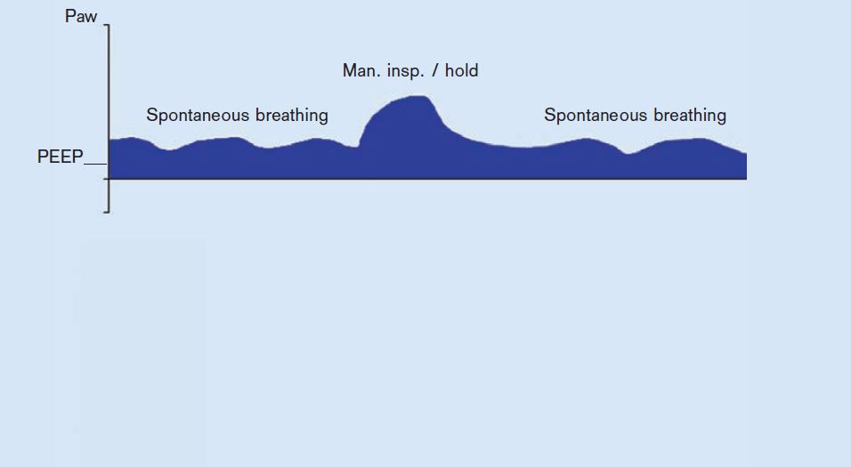
CPAP
|
|
SPN-CPAP with ARM (alveolar recruitment maneuver). Click on the link to see the larger version.
In SPN-CPAP, the patient breathes at the PEEP level (expiratory support) with Psupp = 0 (no inspiratory support). Compared to the atmospheric pressure, the airway pressure is increased during the complete breathing cycle. If the patient is too weak to manage breathing effort completely independently, pressure support (PSV) is an option.
|
Airway Pressure Release Ventilation (PC-APRV)
In PC-APRV, the patient’s spontaneous breathing takes place at the upper pressure level "P
high". P
high is maintained for the duration of T
high (time at high pressure). To execute an active expiration and support CO
2 elimination, the pressure is reduced (to P
low) for the brief period (T
low). The alternation between the two pressure levels is machine-triggered and time cycled. The V
T expired during the relief times (at P
low), results from the pressure difference between P
low and P
high and the lung mechanics. If the Resistance or Compliance of the lung changes, the V
T and thus the V
E also vary.
What is protective ventilation?
Ventilator-associated lung injury is caused by overinflation of some lung areas (volutrauma), excess PIP (barotrauma), underinflation and derecruitment of other areas (atelectrauma), and an increase in inflammatory mediators resulting from alveolar wall stress (biotrauma).
[7]
,
[8]
While no one "recipe" works for all patients or all situations, certain themes have emerged from the research which are probably useful for most patients:
[9]
- Low V
T - 5 to 7 mL/kg ideal body weight (IBW) or predicted body weight (PBW)
- PEEP 5 to 10 cm H
20 to start, more if adverse conditions like high BMI, unhelpful positioning. There is no one right amount- The ideal is to recruit alveoli and increase lung compliance, without decreasing venous return too much.
- Alveolar recruitment maneuvers (ARMs)
Typical ventilator alarms
All current gas machines have VPO (volume, pressure, oxygen) monitoring built in the breathing circuit. Most have agent monitoring as well. Some have spirometry and capnography.
- Pressure in the brathing circuit (High; Continuing high; Below threshold for 15 to 30 seconds (apnea or disconnect); Subatmospheric )
- Low tidal or minute volume
- High respiratory rate
- Reverse flow (may indicate incompetence of expiratory unidirectional valve in the breathing circuit)
-
Apnea/disconnect alarms may be based on
- Chemical monitoring (lack of end tidal carbon dioxide)
- Mechanical monitoring
- Failure to reach normal inspiratory peak pressure, or
- Failure to sense return of tidal volume on a spirometer
- Visual monitoring
- Failure of standing bellows to fill during mechanical ventilator exhalation
- Failure of manual breathing bag to fill during mechanical ventilation (machines with fresh gas decoupling- the Apollo, Fabius GS)
- Auditory monitoring - e.g. lack of breath sounds via precordial stethoscope, lack of sound from ventilator cycling.
New features of modern ventilators
Turbine ventilators
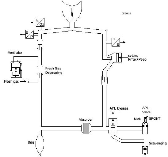
Turbines have been used in the ICU for years, but until recently were not found on anesthesia ventilators. Turbines are an efficient means of generating inspiratory flow quickly, thus they are well-suited to deliver patient-triggered breaths. The TurboVent 2 on Perseus A500 (Dräger) is a compressor/blower which generates the pressure required for ventilation. During inspiration, TurboVent 2 rapidly (in milliseconds) increases the rotation speed to create the set inspiratory pressure (imagine a super powerful hair dryer). It spins at a low rate during expiration also. This maintains PEEP, and also a flow of 0.6 L/min though the breathing circuit, in order to improve mixing of gases in the circuit and lessen the work of breathing of any small spontaneous breaths.
The maximum inspiratory flow is 180 L/min (higher than any current anesthesia ventilator except Servo types). Operation is controlled electronically, based on data from the pressure and flow sensors contained in the breathing system. The ventilation pressure and flow during inspiration and expiration are attained by means of the turbine and the Pmax/PEEP flow valve in the breathing system.
|
|
Perseus breathing circuit. Click on the link to see the larger version.
The turbine draws inspiratory volume from the manual breathing bag as well as from fresh gas flow. The manual breathing bag moves during mechanical ventilation, but in a direction opposite to Apollo. In the Perseus, the manual breathing bag empties during inspiration (like a bellows), and fills during expiration. Thus, the circuit differs from Apollo in two aspects: 1) it lacks a decoupling valve, and 2) the Pmax/PEEPvalve was moved from proximal (upstream) of the expiratory unidirectional valve, to downstream from it.
|
Consequences from the turbine technology:
[10],
[11]
- Allows spontaneous breathing during ventilation at any time.
- Trigger sensitivity and trigger response on same level as high-end ICU respirators.
- Work of breathing as low as on ICU respirators.
- Supports all patients: From neonates to adults.
- Almost unlimited inspiratory flow (peak flow = 180 L/min) to efficiently respond to patient trigger.
- Providing all ventilation modes commonly used in intensive care.
- Does not consume pipeline oxygen for operation (same as the piston)
Piston ventilators
|
Fabius piston. Click on the link to see the larger version.
Piston ventilators use an electric motor to drive a piston, which compresses gas in the breathing circuit, creating the motive force for inspiration to occur. Thus a piston ventilator uses no driving gas, and may be used without depleting the oxygen cylinder in case of oxygen pipeline failure.
Compliance losses are significantly decreased by omitting the compressible bellows. If the corrugated limbs are expanded before the morning electronic self-test of compliance and leaks, the compliance losses out to the Y-piece are known. Thereafter, all that is required is a pressure sensor anywhere in the breathing circuit to deliver accurate V
T.
|
|
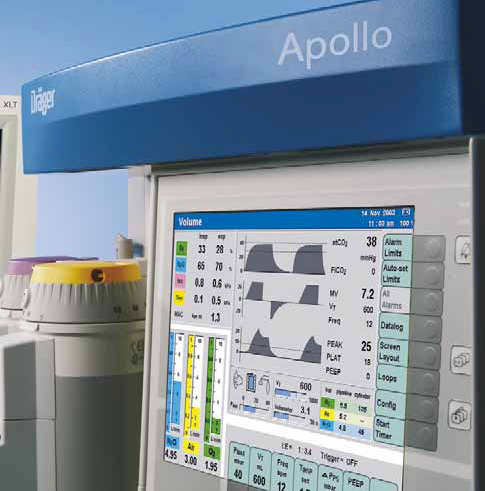
Apollo interface. Click on the link to see the larger version.
In the Apollo, the bellows operation is not visible. The anesthetist relies on flow, pressure, and capnography waveforms (and the movement of the breathing bag during mechanical ventilation as a result of fresh-gas decoupling [see section on fresh gas decoupling below on this page]) to guard against disconnects or other problems.
|
|
Piston ventilator window Fabius GS. Click on the link to see the larger version.
The Fabius GS has a piston ventilator similar to the Apollo, but the bellows travel vertically, and its movement is continuously visible through a window to the left of the flowmeter bank.
|
Piston ventilators have positive and negative pressure relief valves built in. If the pressure within the piston reaches 75
+ 5 cm H
2O, the positive pressure relief valve opens. If the pressure within the piston declines to -8 cm H
2O, the negative pressure relief valve opens, and room air is drawn into the piston, protecting the patient from NEEP (negative end-expiratory pressure).
There are several
advantages to a piston ventilator system (Apollo & Fabius GS):
- Quiet
- No PEEP (2-3 cm water are mandatory on standing bellows ventilators due to the design of the ventilator spill valve)
- Precise delivered tidal volume due to compliance and leak compensation, fresh gas decoupling, and the rigid piston design. There are less compliance losses with a piston as compared to a bellows.
[12]
- Measuring compliance and leaks with a transducer near the piston is accurate.
- Electricity is the driving force for the piston, so if oxygen pipeline pressure fails and one must rely on oxygen from the emergency cylinder, mechanical ventilation may continue (without exhausting the cylinder oxygen simply to drive the bellows).
The
disadvantages of the piston design include:
- Quiet (less easy to hear regular cycling)
- Loss of the familiar visible behavior of a standing bellows during disconnects, or when the patient is breathing over and above the ventilator settings.
- The piston ventilator design cannot easily accommodate nonrebreathing circuits (although the same can be validly argued in regards to any newer model breathing circuit).
- Potential for NEEP (negative end-expiratory pressure)
Flexibility
The appearance of pressure control ventilation is a major advantage, allowing patients to be ventilated efficiently who were very difficult with volume control mode, such as patients with ARDS or morbid obesity. PCV also allows safe ventilation when excessive pressure must be strictly avoided; such as neonates and infants, and emphysematous patients. The appearance of modes which are capable of supporting the patient with spontaneous respirations (like PSV, SIMV, CPAP, and Volume Guarantee) extends our capabilities further.
Accuracy at lower tidal volumes
(This section only refers to increasing V
T accuracy during volume control ventilation, which is used less frequently at present.)
Factors contributing to a discrepancy between set and delivered V
T in VCV are especially acute in pediatrics and include
- large compression volume of the circle system relative to the infant's lung volume
- leaks around uncuffed endotracheal tubes
- effects of fresh gas flow on delivered tidal volume
- mechanical difficulty of setting a small tidal volume using an adult bellows assembly
Because of the greatly increased accuracy in tidal volume delivery achieved through compliance and leak testing and compensation, modern ventilators have an unprecedented V
T range. Fabius, Apollo, Aestiva, Perseus, & Aisys can deliver accurate V
T as low as 20 mL in VCV.
[13] They can ventilate smaller patients in VCV mode much more accurately than any previous anesthesia ventilator could. Anything that lessens the need for non-rebreathing (Mapleson & Bain) circuits enhances safety, since users will no longer have to disassemble and reconfigure to a non-rebreathing circuit for a child in the middle of several adult cases. PCV is of course much more commonly used in children and adults, as stated, which also plays a role in the decreased need for non-rebreathing circuits. Regardless of mode, it is wise to substitute a pediatric circuit for V
T less than 200 mL, in order to lessen compliance losses to the corrugated hoses.
Compliance and leak testing
An electronic leak and compliance test must be repeated every time the circuit type is changed (e.g. adult circle to pediatric circle, or adult to long circuit). This test is part of the electronic self-test portion of the morning checklist.
The placement of the sensor used to compensate tidal volumes for compliance losses and leaks has some interesting consequences. All flow and volume sensors are somewhat sensitive to moisture accumulation, which is more likely due to rebreathing as fresh gas flows decrease.
Apollo, Perseus, and Aisys test compliance and leaks of all components to the Y-piece via pressure transducer and flow sensors within the internal circuitry near the bellows. Here the sensors are somewhat protected from moisture. Aisys relies on an optional (but recommended) condenser to keep the breathing circuit dry and protect the flow sensors; Perseus uses a heated absorber head.
Fresh gas decoupling versus compensation
Modern ventilators compensate delivered tidal volume for changes in fresh gas flow (FGF). In older ventilators the delivered tidal volume is the sum of the volume delivered from the ventilator bellows, and the fresh gas flow delivered during the inspiratory phase of each breath. Thus, delivered tidal volume may change as FGF is changed.
|
For example, consider a patient with a FGF of 4 L/min, a respiratory rate of 10, inspiratory:expiratory (I:E) ratio of 1:2, and a tidal volume of 700 mL. During each minute, the ventilator spends 20 seconds in inspiratory time and 40 seconds in expiratory time (1:2 ratio). During this 20 seconds, the fresh gas flow is 1,320 mL (4000 mL/min FGF times 20/60 sec). Each of the 10 breaths of 700 mL is augmented by 132 mL of fresh gas flowing while the breath is being delivered, so the total
delivered tidal volume is 832 mL/breath. This 19% increase is reasonably unimportant since we target settings to etCO
2.
But what happens if we decrease the fresh gas flow? Assume the same parameters, but a FGF of 1,000 mL/min. During each minute, the ventilator spends 20 seconds in inspiratory time and 40 seconds in expiratory time (1:2 ratio). During this 20 seconds, the fresh gas flow is 330 mL (1000 mL/min FGF times 20/60 sec). Each of the 10 breaths of 700 mL is augmented by 33 mL of fresh gas flowing while the breath is being delivered, so the total
delivered tidal volume is 733 mL/breath. This means that changing FGF from 4,000 mL/min to 1,000 mL/min,
without changing ventilator settings, has resulted in a 14% decrease in delivered tidal volume (832 to 733 mL). It would not be surprising if the end tidal carbon dioxide rose as a result.
The situation is more acute with an older anesthesia ventilator in children. Assume a 20 kg patient with a FGF of 4 L/min, a respiratory rate of 20, inspiratory:expiratory ratio of 1:2, and a tidal volume of 200 mL. During each minute, the ventilator spends 20 seconds in inspiratory time and 40 seconds in expiratory time (1:2 ratio). During this 20 seconds, the fresh gas flow is 1,320 mL (4000 mL/min FGF times 1/3). Each of the 20 breaths of 200 mL is augmented by 66 mL of fresh gas flowing while the breath is being delivered, so the total
delivered tidal volume is 266 mL/breath. This is a 33% increase above what is set on the ventilator.
We now decrease the FGF from 4 to 1 L/min for the same 20 kg child, (RR 20, I:E ratio of 1:2, and V
T 200 mL). During each minute, the ventilator spends 20 seconds in inspiratory time and 40 seconds in expiratory time (1:2 ratio). During this 20 seconds, the fresh gas flow is 333 mL (1000 mL/min FGF times 1/3). Each of the 20 breaths of 200 mL is augmented by 16.5 mL of fresh gas flowing while the breath is being delivered, so the total
delivered tidal volume is 216 mL/breath. This is a 23% decrease in V
T (266 to 216 mL/breath) caused solely by changing FGF, and without altering vent settings.
|
|
|
Fabius GS ventilator schematic. Click on the link to see the larger version.
There are two approaches to dealing with the problem. The Dräger Apollo and Fabius GS use fresh gas decoupling. Fresh gas is diverted by a decoupling valve to the manual breathing bag during inspiration, and is thus not added to the delivered tidal volume. Thus, fresh gas decoupling helps ensure that the set and delivered tidal volumes are equal.
|
The visual appearance is unusual as compared to a bellows ventilator. The action of the piston closes a one-way (decoupling) valve, diverting FGF to the manual breathing bag during the inspiratory cycle.
- the manual breathing bag, normally quiescent during mechanical ventilation in a standing bellows ventilator, moves with each breath
- the manual breathing bag movement is opposite to the movement seen in a standing bellows- the manual breathing bag
inflates during inspiration (due to fresh gas flow), and
deflates during expiration as the contents empty into the absorbent and move on towards the patient.
With fresh gas decoupling, if there is a disconnect, the manual breathing bag rapidly deflates, since piston retraction draws gas from it.
The second approach is fresh gas compensation, which is utilized in the Aisys, Aestiva, Avance, and Aespire. The volume and flow sensors provide feedback which allows the ventilator to adjust the delivered tidal volume so that it matches the set tidal volume, in spite of changes in the total fresh gas flow.
A similar approach is taken in the Dräger Perseus. The breathing circuit is like Apollo, but has no fresh gas decoupling valve. The placement of the fresh gas flow (FGF) inlet between turbine and inspiratory unidirectional valve means that FGF is not diverted to the reservoir bag during inspiration (as in Apollo or Fabius) but is added to V
T during inspiration. Data from flow and pressure sensors is used to control turbine speed. The Pmax/PEEP valve, which stops inspiration when the desired V
T and inspiratory time (Ti) are achieved. In Perseus (opposite to Appollo or Fabius), the bag behaves like a standing bellows- deflating during inspiration and inflating during expiration.
Suitability for low flows
Low fresh gas flow is desirable to reduce pollution and cost of volatile agents and nitrous oxide, preserve tracheal heat and moisture, prevent soda lime granules from drying, and preserve patient body temperature. Factors which enhance the safety and efficiency of low FGF in modern ventilators include:
- Compliance and leak testing
- Automatic leak detection
- Fresh gas compensation or decoupling
- Warmed absorber heads (Perseus); Water condenser (Aisys)
- Accumulation of condensed exhaled water vapor is a problem for most breathing circuits. Use of low flows can make the problem more acute.
- Low volume absorber heads/breathing circuits (allows faster equilibration of dialed and delivered agent concentration). A traditional sized absorber head like the Aestiva (2.7 L in canisters alone) is roughly twice the volume of any of the newer designs.
- Apollo 1.5 L canister
- Fabius GS 1.5 L (2.8 L + bag for entire breathing system)
- Perseus 1.5 L canister (2.2 L total breathing circuit volume)
- Aisys, Avance, Aespire 800 g absorbent (entire breathing circuit volume 2.7 L including absorbent in mechanical ventilator mode, 1.2 L in bag mode)
- Low fresh gas flows allowed by gas machine- most no longer have mandatory minimum oxygen flows of 200-300 mL/min
- Low flow wizard (i.e. econometer)- an electronic monitor that gives indications when fresh gas flow is excessive or too low by monitoring gas volume passing through the scavenger (Apollo, Perseus, A9)
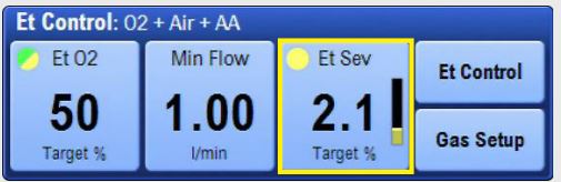
- End-tidal Control- ensures delivered oxygen and anesthetic agent reach and maintain at set safe levels rapidly, even at FGF less than 1 L/min
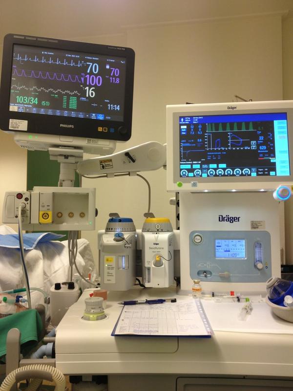
Current models
Dräger Perseus A500
|
Perseus. Click on the link to see the larger version.
|

|
Example control settings for Perseus in PC-SIMV mode. Click on the link to see the larger version.
The Perseus is a modern turbine ventilator. The turbine ventilator is electrically driven and electronically controlled. It works without compressed gas. Ventilation modes are extensive, including the first availability of APRV and CPAP on an anesthesia ventilator. Much like an ICU ventilator in the sophistication of its controls: ventilation can be optimized for a very wide range of patients and situations. However, it does place a learning burden on anesthetists, who must learn the new controls and their interactions.
- V
T 20-2000 mL
- Freq 3-100 bpm
- PEEP to 35 cm water
- Pressure limit 80 cm water
- Inspiratory flow up to 180 L/min
|
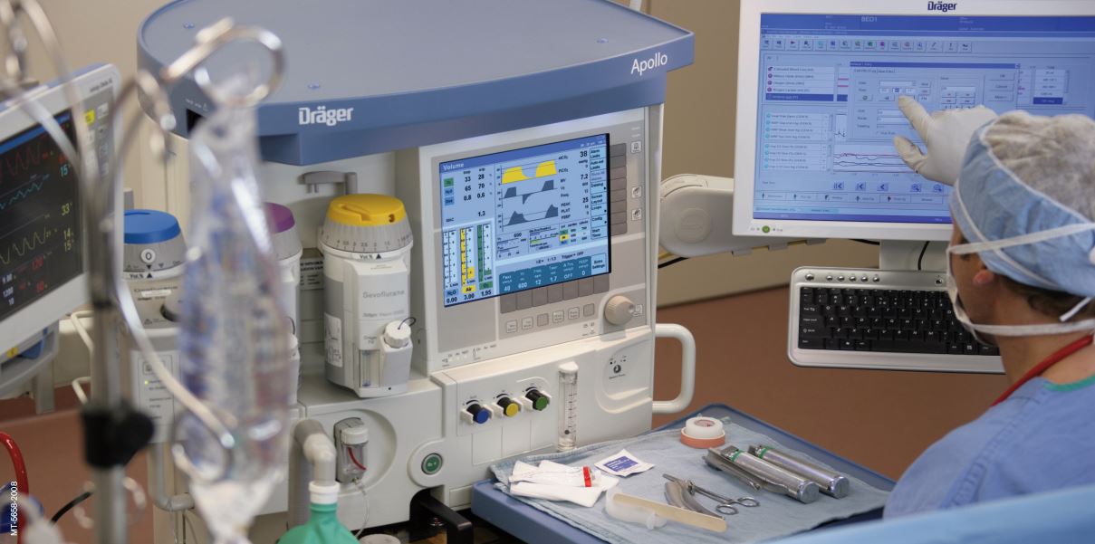
Dräger Apollo
|
Apollo. Click on the link to see the larger version.
|
|
Apollo controls. Click on the link to see the larger version.
The Apollo is a modern piston ventilator with spirometry monitoring. The piston ventilator is electrically driven and electronically controlled, fresh gas decoupled. Ventilation modes Manual, spontaneous, VCV, PCV, SIMV-Vol, SIMV-PC, PSV. Optional/Synchronization: Pressure Support (PS).
- V
T 20-1400 mL
- Freq 3-80 bpm
- I:E ratio 5:1 (max)
- Inspiratory Pause 0-60%
- PEEP to 20 cm H
2O
- Adjustable Peak flow, plateau time
- Pressure limit 70 cm H
2O
- Inspiratory flow (pressure control mode) up to 150 L/min
|
GE Aisys
|
Aisys. Click on the link to see the larger version.
|
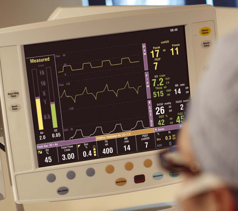
|
Aisys controls. Click on the link to see the larger version.
The Aisys has a dual circuit, ascending bellows 7900 ventilator. Modes include VCV, PCV, PC-VG, SIMV-Vol, SIMV-Press, and PSV-Pro. Maximum flow is 120 L/min. Maximum pressure is 60 cm H
2
O. PEEP 0-30 cm H
2
O. Inspiratory/expiratory ratio can be selected from 2:1 to 1:8. The vent features tidal volume compensation, one switch activation from manual to mechanical ventilation,two key presses to total standby (end case), and a cardiac bypass case mode. The Advanced Breathing System (ABS™) has a minimal number of parts and tube connections, which greatly reduces the potential for leaks and misconnects. It is easy to disassemble (no tools), fully autoclavable, and latex-free (as are most modern anesthesia machines).
|
|
End tidal Control. Click on the link to see the larger version.
The Aisys CS2 features End Tidal Control, by which the users sets targets for expired agent, oxygen,and minimum fresh gas flows, and the machine manipulates FGF and agent concentration to achieve and maintain these targets more quickly and with less control interactions with the operator.
|
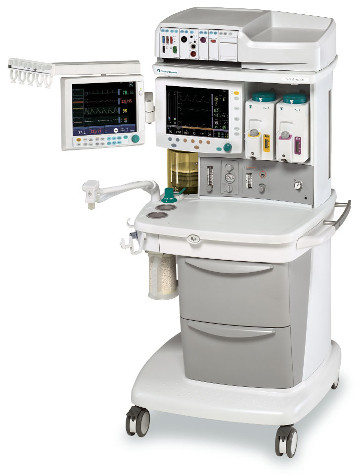
GE Avance
|
Avance. Click on the link to see the larger version.
The Avance uses the same 7900 ventilator and breathing system as the Aisys. The difference in the machines is that the Avance uses conventional vaporizers.
|
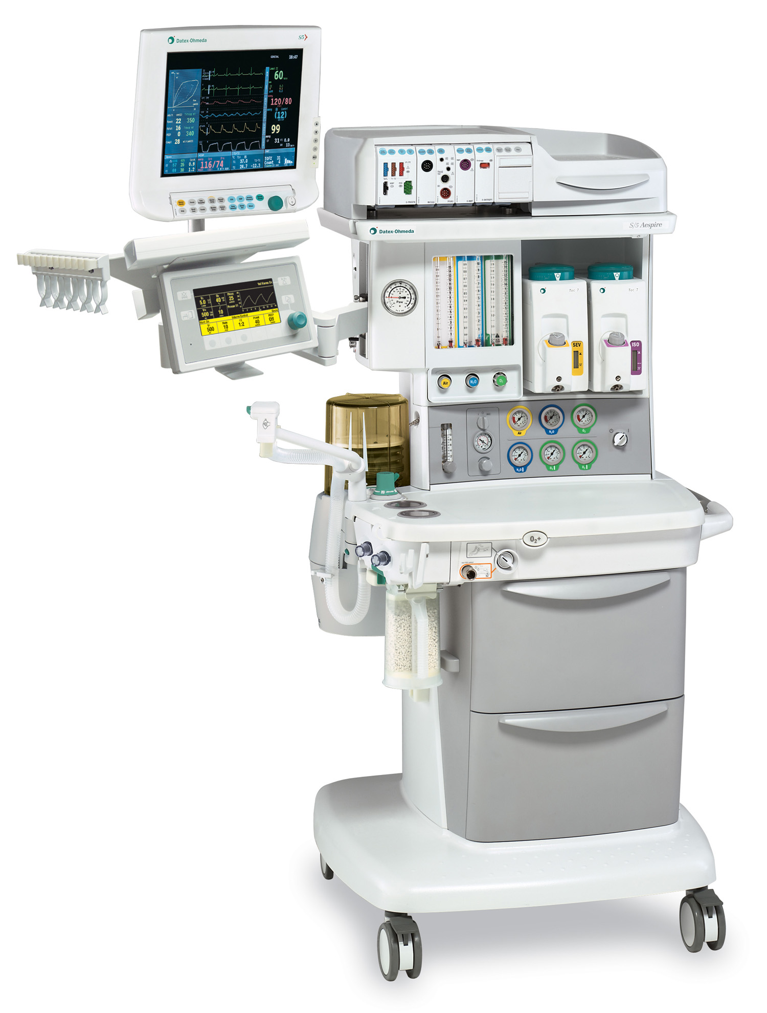
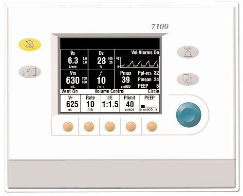
GE Aespire
|
Aespire. Click on the link to see the larger version.
|
|
Aespire ventilator controls. Click on the link to see the larger version.
Aespire (and Aestiva) share the current GE 7100 ventilator. Aespire shares the Advanced Breathing System used by Aisys and Avance. Aespire uses traditional flowmeters for FGF (needle valve, glass flowtube). The 7100 ventilator features VCV, PCV, and electronic PEEP. V
T range is 45-1500 mL. Maximum inspired pressure is 50 cm water.
|
Mindray A9

|
Mindray A9. Click on the link to see the larger version.
Modern servo type ventilator with a wide selection of modes (VCV, SIMV-VC, PCV, PCV-VG, SIMV-PC, SIMV-VG, CPAP/PSV, APRV). Maximum inspiratory flow 180 L/min; V
T 10-2000 mL (VCV).
Features include lung recruitment & protective ventilation toolkits, high-flow nasal cannula, agent usage calculation, volume exchanger (reflector) in breathing system, low flow optimizer, injector vaporizers, electronic gas mixer for FGF. Automatic Controlled Anesthesia automatically adjusts the FGF & vaporizer output to quickly achieve the preset target end-tidal agent and inspiratory oxygen concentration).
|
Maquet Flow-e

|
Maquet Flow-e. Click on the link to see the larger version.
Maquet Flow-e & Flow-I use a modern servo type ventilator with VCV, PCV, PSV, SIMV, & PRVC. Maximum inspiratory flow 200 L/min; V
T 20-2000 mL (VCV).
Maquet suggests that patients should be ventilated using Pressure Regulated Volume Control (PRVC) unless specified otherwise. PRVC delivers a set tidal volume but automatically adjusts the inspiratory pressure on a breath-to-breath basis to achieve it with the lowest pressure possible. This adaptive strategy provides lung-protective ventilation, especially for patients with fluctuating compliance or resistance, while ensuring consistent gas exchange.
Features include active hypoxic guard, lung recruitment, agent usage calculation, volume reflector in breathing system, low flow optimizer, injector vaporizers, electronic gas mixer for FGF. Automatic Gas Control (AGC)- users sets the targeted inspired oxygen, end-tidal anesthetic agent levels and required speed, AGC Controlled Anesthesia automatically adjusts the FGF & vaporizer output to quickly achieve the preset targets.
|
Older or obsolete models
How do you determine that a machine needs replacement?
[14]
GE Aestiva
Paragon
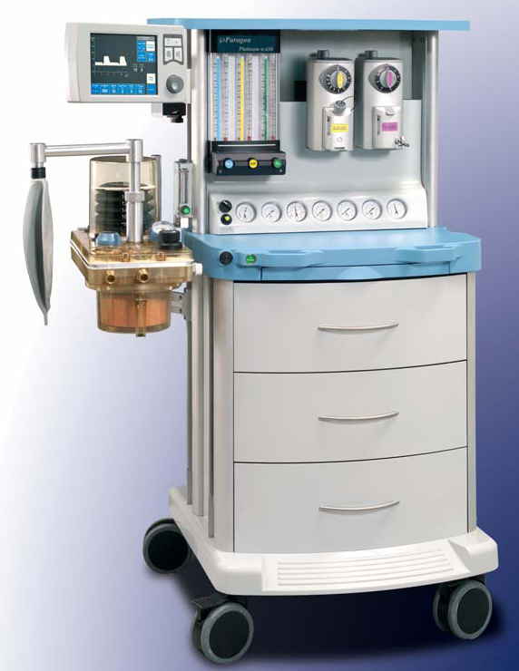
|
Paragon. Click on the link to see the larger version.
|
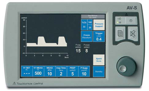
|
AV-S ventilator. Click on the link to see the larger version.
The breathing circuit is latex free, like most modern machines. Absorbent capacity is 1.3 kg of loose or pre-packed absorbent. The standing bellows may be driven by oxygen or air.
The AV-S ventilator on the Paragon Platinum SC430 offers integrated FGF compensation, VPO (volume, pressure, oxygen) and spirometry monitoring, and automated compliance and leak testing. VCV (20-1600 mL/breath), PCV (to 70 cm H
2O), and PSV modes are available with integrated electronic PEEP. Insp/Exp ratio is selectable from 1:0.3 to 1:8. Pmax 80 cm H
2O).
|
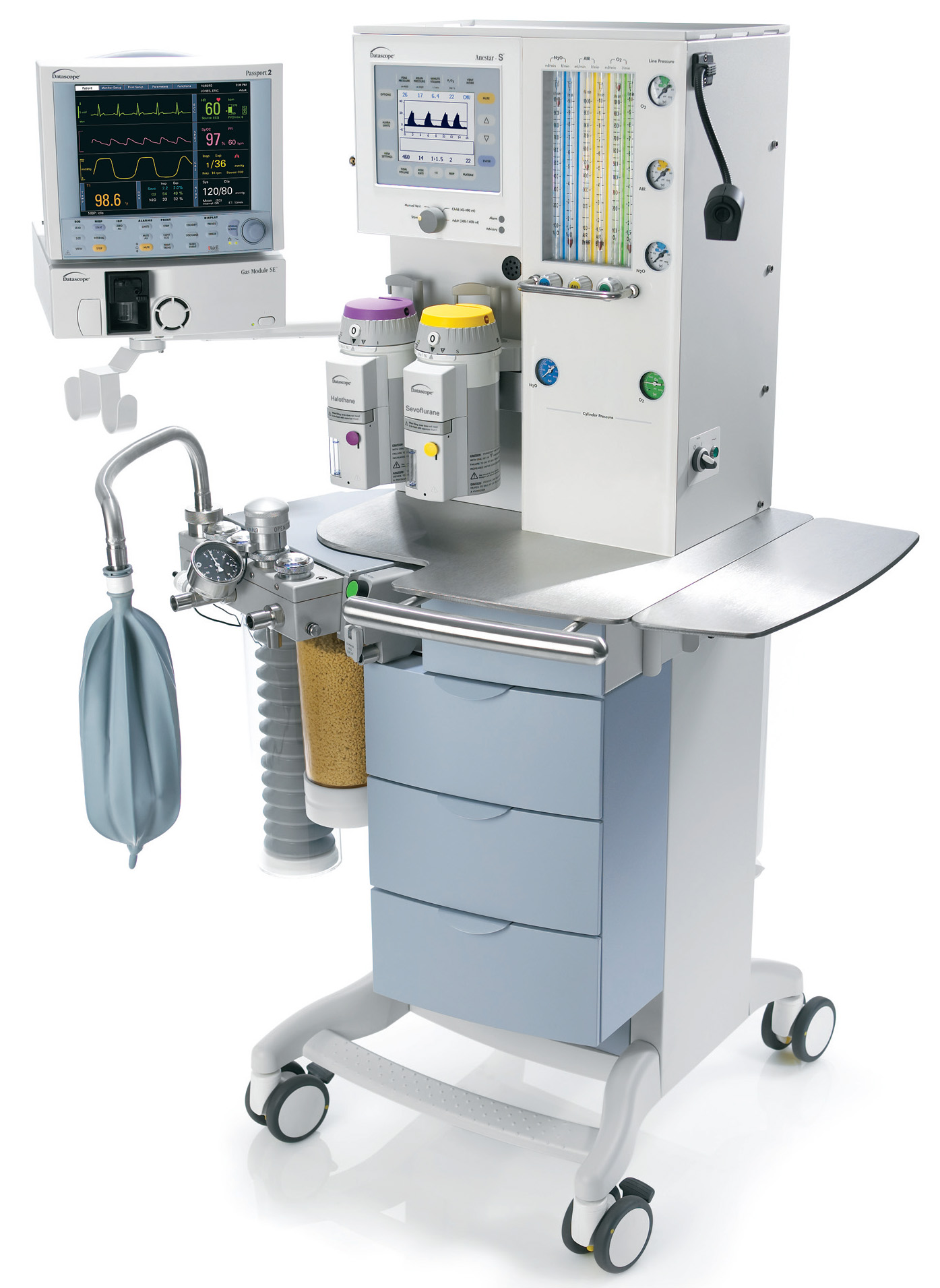
Anestar-S
|
|
Anestar. Click on the link to see the larger version.
The Anestar ventilator is a hanging bellows, gas-driven, electronically controlled ventilator. It offers VCV, PCV, and PSV modes. V
T is 10-9999 mL. Insp/Exp ratio is 3:1 to 1:5. The breathing circuit is warmed and V
T compensation is achieved through fresh-gas decoupling. Flow sensors are hot-wire anemometers (like most Draeger machines). The internal volume of the breathing system is 2.5 L (of which 1.4 L is absorbent).
|
Fabius GS ventilator
|
Fabius GS Ventilator controls. Click on the link to see the larger version.
The Fabius GS ventilator is an electronically controlled, electrically driven piston ventilator. It consumes no drive gas. The piston is continuously visible. Operating parameters include
- V
T 20-1400 mL
- Freq 4-60 bpm
- I:E ratio 4:1 to 1:4
- Inspiratory Pause 0-50%
- PEEP to 20 cm H
2
O
- Adjustable Peak flow, plateau time, insp flow (max 75 L/min)
- Pressure limit 15-70 cm H
2
O
- Inspiratory pressure (pressure control mode) 5-60 cm H
2
O
- Inspiratory flow (pressure control mode) 10-75 L/min
|
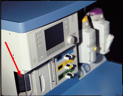
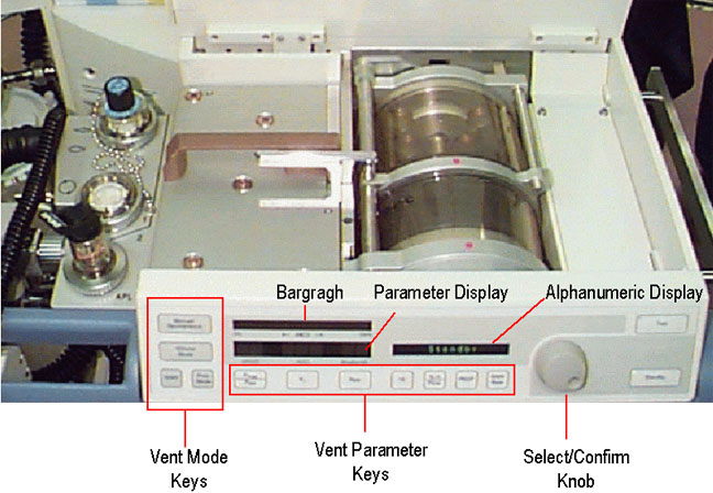
ADU ventilator
|
ADU ventilator controls. The left arrow shows the Bag/Auto and APL valve location. The right arrow shows the location of the thumbwheel and buttons by which ventilator settings are changed. Click on the link to see the larger version.
|
|
D-Lite sensor. Click on the link to see the larger version.
The ADU ventilator has a suite of useful and unique features, many of which it shares with other modern anesthesia ventilators. Single switch activation (setting the Bag/Vent switch to "Auto") is all that is needed to start mechanical ventilation (all new ventilators are activated in this way). Entering the patient’s weight will suggest appropriate ventilator settings. V
T is adjusted to compensate for changes in fresh gas flow, and total (absorber head and corrugated limbs) breathing circuit compliance losses through the D-Lite sensor at the elbow.
The ventilator can utilize either oxygen or air as a driving gas, and will switch automatically if oxygen pipeline pressure is lost. Volume-control, pressure control, synchronized intermittent mandatory ventilation (SIMV-Vol),and PSV modes are offered, along with integrated electronic PEEP.
The pressure control mode should be very useful to increase delivered tidal volume when lung compliance is low (laparoscopic procedures, obesity, pregnancy) or when high peak inspiratory pressures must be avoided (pediatric patients, laryngeal mask ventilation, emphysema). Flow-volume (resistance) or pressure-volume (compliance) loops may be displayed breath-by-breath.
|
Dräger Divan ventilator
|
Divan Controls (front panel). Click on the link to see the larger version.
The Dräger Divan ventilator is a modern piston ventilator, offering features such as: pressure control mode, SIMV, correction for compliance losses, and integrated electronic PEEP. Unlike the ADU, newer Dräger absorber heads warm the gases in the breathing circuit. Also unique is that fresh gas flow does not add to delivered tidal volume ("fresh gas decoupling"- see New features above on this page). The Divan is limited to a pressure of 70 cm water- so it cannot ventilate patients in VCV mode beyond this pressure (although, again, it is possible and even perhaps preferable to ventilate the ARDS patient with pressure control mode). It is installed on the Narkomed 6000/6400.
Unlike most other anesthesia ventilators, there are no visible bellows on the NM6000 Divan ventilator. It is unique among current models in having a horizontal piston which is hidden within the writing surface of the gas machine. To provide a visible indication of lung inflation, fresh gas is diverted to the manual breathing bag, which inflates during mechanical ventilator inspiration, and deflates during expiration. A disconnect will cause the manual breathing bag to gradually lose volume (in addition to activating other apnea alarms). A pressure transducer within the ventilator measures compliance losses and leaks in the total breathing circuit (absorber head and corrugated limbs).
The Fabius GS has a piston ventilator as well, but the piston is mounted vertically to the left of the flowmeters and is visible through a window.
|
Dräger AV-E and AV-2
|
AV2 controls. Click on the link to see the larger version.
Classification: pneumatically and electrically powered, double circuit, pneumatically driven, ascending bellows, time cycled, electronically controlled, V
T preset vent. Incorporates Pressure Limit Controller (PLC) which allows maximum peak inspiratory pressure (PIP) adjustment from 10-110 cm water. Inspiratory flow control must be set properly (like the Ohmeda 7800), so that driving gas flow does not create an inspiratory pause. Standard on Narkomed 2A, 2B, 2C, 3, 4, and Narkomed (not Fabius) GS.
|
Ohmeda 7000
|
Ohmeda 7000 controls. Click on the link to see the larger version.
Same classification as Dräger AV-E
except it is minute-volume preset (unique among anesthesia ventilators). V
T
cannot be set directly, it is calculated from settings of V
E and respiratory rate (V
E = RR x V
T). Inspiratory flow stops when set V
T of driving gas has been delivered to the driving circuit side of the bellows chamber or if pressure greater than 65 cm water is attained.
|
Ohmeda 7800
|
Ohmeda 7800 controls. Click on the link to see the larger version.
This ventilator or the older Ohmeda 7900 Smart-Vent were standard on newer Excel or Modulus machines. Same classification as Dräger AV2 ventilator; V
T preset. Tidal volume, respiratory rate, inspiratory flow and pressure limit controls are present.
|
Older Ohmeda 7900 "SmartVent"
|
Ohmeda 7900 controls. Click on the link to see the larger version.
Same classification as Dräger AV ventilator, V
T preset. Microprocessor control delivers set V
T, in spite of changes in fresh gas flow, small leaks, and absorber or bellows compliance losses proximal to the sensors. These flow sensors are placed between corrugated plastic breathing circuit and the absorber head, in both limbs. These are connected to pressure transducers in the ventilator. Compliance losses in the breathing circuit corrugated hoses are not corrected, but these are a relatively small portion of compliance losses.
The first "modern" ventilator- it offered such desirable features as integrated electronic PEEP, and PCV. It has been reported that the sensors can be quite sensitive to humidity, causing ventilator inaccuracy or outright failure. The problem may be more likely when active airway humidifiers are used.
[15],
[16]
Controls are similar to the 7800. Users should be vigilant for cracked tubing in the flow sensors, which are located where the breathing circuit corrugated hoses attach to the absorber head. Leaks here have been reported to cause inability to ventilate, either mechanically or manually. When these failures occur, the ventilator may indicate alarm messages like "V
T" or "Apnea", rather than "Check sensor". Flow sensor tubing must be vertical, must be changed regularly, and sensors must be in the proper side (inspiratory or expiratory). Although the sensor plugs are keyed by size and shape, if both sensors come off the absorber head when the circuit is changed they can be inadvertently replaced on the wrong side.
|